

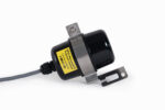
Barometro NRG BP65

NRG BP65 è il sensore barometrico preciso per monitoraggio meteorologico, impianti solari ed eolici. Consumi ridotti, compensazione termica e affidabilità professionale.

Marchio NRG SYSTEMS

Descrizione prodotto

Sensore Barometrico NRG BP65

Precisione superiore per il monitoraggio meteorologico e la valutazione delle risorse energetiche

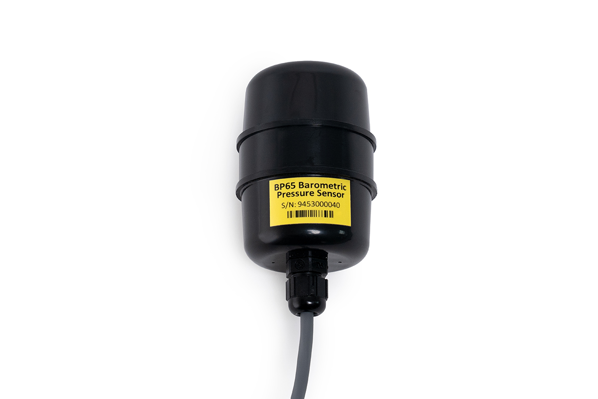
Il NRG BP65 è un sensore di pressione barometrica di nuova generazione progettato per applicazioni meteorologiche professionali, monitoraggio solare e studi anemologici. Evoluzione diretta del consolidato BP60, combina accuratezza, affidabilità a lungo termine e facilità di integrazione, rendendolo una delle soluzioni più interessanti sul mercato per il rilevamento della pressione atmosferica.Grazie all’elemento sensibile ad alta precisione e alla compensazione termica nativa, il BP65 reagisce rapidamente alle variazioni di temperatura interna, garantendo misure stabili e affidabili anche in condizioni ambientali particolarmente critiche. Il robusto involucro protegge il sensore dagli agenti atmosferici, assicurando prestazioni costanti nel tempo.

Cosa rende unico il NRG BP65

A differenza di molti sensori concorrenti, il BP65 offre una combinazione ideale di precisione elevata, basso consumo energetico e verifica delle prestazioni certificata in fabbrica, caratteristiche fondamentali per installazioni remote e sistemi alimentati a energia solare.

Punti di forza:
  • Elevata accuratezza per applicazioni meteorologiche professionali.
  • Compensazione automatica della temperatura per una risposta immediata ai cambiamenti ambientali.
  • Consumo estremamente ridotto (solo 1 mA), ideale per stazioni meteorologiche autonome.
  • Certificato di verifica prestazionale fornito di serie.
  • Disponibilità di calibrazione multipunto per applicazioni che richiedono la massima precisione.
  • Sostituzione diretta del modello BP60 senza modifiche all’impianto.
  • Possibilità di cavi fino a 110 metri e staffe dedicate per installazioni su torre.

Applicazioni

Il sensore NRG BP65 è particolarmente indicato per:

  • Monitoraggio anemologico ed eolico
  • Monitoraggio delle risorse solari
  • Stazioni meteorologiche professionali
  • Calcolo della densità dell’aria
  • Studi di produzione energetica annuale (AEP)
  • Impianti fotovoltaici e sistemi di energia rinnovabile
  • Installazioni remote alimentate a pannelli solari

Grazie alla sua affidabilità e alla qualità costruttiva NRG Systems, il BP65 rappresenta una scelta sicura per tecnici, sviluppatori di impianti energetici, società di ingegneria e operatori del settore meteorologico che necessitano di dati accurati e continuità operativa nel lungo periodo.

Specifiche tecniche

1.5M CABLE (#19126) 1.5M CABLE, CALIBRATED (#19127) 67M CABLE (#19128) 90M CABLE (#19129) 110M CABLE (#19130)
Description
Sensor type Analog barometric pressure sensor based on piezo resistive silicon membrane Analog barometric pressure sensor based on piezo resistive silicon membrane Analog barometric pressure sensor based on piezo resistive silicon membrane Analog barometric pressure sensor based on piezo resistive silicon membrane Analog barometric pressure sensor based on piezo resistive silicon membrane
Applications
  • Wind and Solar resource assessment and monitoring
  • Meteorological studies
  • Environmental monitoring
  • Wind and Solar resource assessment and monitoring
  • Meteorological studies
  • Environmental monitoring
  • Wind and Solar resource assessment and monitoring
  • Meteorological studies
  • Environmental monitoring
  • Wind and Solar resource assessment and monitoring
  • Meteorological studies
  • Environmental monitoring
  • Wind and Solar resource assessment and monitoring
  • Meteorological studies
  • Environmental monitoring
Sensor range
  • 500 hPa to 1100 hPa (14.765 to 32.483 inches Hg)
  • 500 hPa to 1100 hPa (14.765 to 32.483 inches Hg)
  • 500 hPa to 1100 hPa (14.765 to 32.483 inches Hg)
  • 500 hPa to 1100 hPa (14.765 to 32.483 inches Hg)
  • 500 hPa to 1100 hPa (14.765 to 32.483 inches Hg)
Signal conditioning module
  • SymphoniePRO: P-SCM #9130, 0 to 5 V, SE Input, Pulsed 5V EXC
  • SymphoniePRO: P-SCM #9130, 0 to 5 V, SE Input, Pulsed 5V EXC
  • SymphoniePRO: P-SCM #9130, 0 to 5 V, SE Input, Pulsed 5V EXC
  • SymphoniePRO: P-SCM #9130, 0 to 5 V, SE Input, Pulsed 5V EXC
  • SymphoniePRO: P-SCM #9130, 0 to 5 V, SE Input, Pulsed 5V EXC
Output signal
Signal type
  • Linear analog voltage
  • Linear analog voltage
  • Linear analog voltage
  • Linear analog voltage
  • Linear analog voltage
Transfer function
  • Absolute Pressure in hPa = (Voltage x 243.90857 + 493.91990 typical
  • Absolute Pressure in inches Hg = (Voltage x 7.202616) + 14.585446 typical Note: Transfer function above applies to 1.5-meter cable. For sensors with cable lengths longer than 1.5 meters, subtract 0.015949406 hPa (0.00047098563 inHg) per additional meter.
Please refer to your calibration report.
  • Absolute Pressure in hPa = (Voltage x 243.89926 + 494.73295 typical
  • Absolute Pressure in inches Hg = (Voltage x 7.202341) + 14.609455 typical
    Note: Transfer function above applies to 1.5-meter cable. For sensors with cable lengths longer than 1.5 meters, subtract 0.015949406 hPa (0.00047098563 inHg) per additional meter.
  • Absolute Pressure in hPa = (Voltage x 243.89926 + 494.73295 typical
  • Absolute Pressure in inches Hg = (Voltage x 7.202341) + 14.609455 typical
    Note: Transfer function above applies to 1.5-meter cable. For sensors with cable lengths longer than 1.5 meters, subtract 0.015949406 hPa (0.00047098563 inHg) per additional meter.
  • Absolute Pressure in hPa = (Voltage x 243.89926 + 494.73295 typical
  • Absolute Pressure in inches Hg = (Voltage x 7.202341) + 14.609455 typical
    Note: Transfer function above applies to 1.5-meter cable. For sensors with cable lengths longer than 1.5 meters, subtract 0.015949406 hPa (0.00047098563 inHg) per additional meter.
Accuracy Uncertainty (k = 2):
  • ± 1.12 hPa (@ 25°C)
  • ± 2.13 hPa (-20 to 40°C)
Uncertainty (k = 2):
  • ± 0.83 hPa (@ 25°C)
  • ± 1.83 hPa (-20 to 40°C)
Uncertainty (k = 2):
  • ± 1.12 hPa (@ 25°C)
  • ± 2.13 hPa (-20 to 40°C)
Uncertainty (k = 2):
  • ± 1.12 hPa (@ 25°C)
  • ± 2.13 hPa (-20 to 40°C)
Uncertainty (k = 2):
  • ± 1.12 hPa (@ 25°C)
  • ± 2.13 hPa (-20 to 40°C)
Electrical time constant
  • 1 second
  • 1 second
  • 1 second
  • 1 second
  • 1 second
Calibration
  • Each sensor individually tested to meet or exceed published specifications. A certificate of quality is available for each individual sensor.
  • Each sensor individually calibrated.
  • A certificate of calibration is available for each individual sensor.
  • Performed at ISO/IEC 17025:2017-certified facility.
  • Traceable to National Institute for Standards and Technology (NIST) standards.
  • Each sensor individually tested to meet or exceed published specifications. A certificate of quality is available for each individual sensor.
  • Each sensor individually tested to meet or exceed published specifications. A certificate of quality is available for each individual sensor.
  • Each sensor individually tested to meet or exceed published specifications. A certificate of quality is available for each individual sensor.
Output signal range
  • 0.020 to 2.480 VDC
  • 0.020 to 2.480 VDC
  • 0.020 to 2.480 VDC
  • 0.020 to 2.480 VDC
  • 0.020 to 2.480 VDC
Turn on time
  • < 20 ms
  • < 20 ms
  • < 20 ms
  • < 20 ms
  • < 20 ms
Resolution
  • 0.0092 hPa (0.0027 inHg)
  • 0.0092 hPa (0.0027 inHg)
  • 0.0092 hPa (0.0027 inHg)
  • 0.0092 hPa (0.0027 inHg)
  • 0.0092 hPa (0.0027 inHg)
Drift
  • ± 1.0 hPa per year
  • ± 1.0 hPa per year
  • ± 1.0 hPa per year
  • ± 1.0 hPa per year
  • ± 1.0 hPa per year
Power requirements
Supply voltage
  • 5 to 15 VDC
  • 5 V pulsed excitation recommended Note: When using a 3rd party data logger capable of pulsed excitation operation, please allow a minimum of 25ms settling time between the initial power-up and reading the sensor output voltage.
  • 5 to 15 VDC
  • 5 V pulsed excitation recommended Note: When using a 3rd party data logger capable of pulsed excitation operation, please allow a minimum of 25ms settling time between the initial power-up and reading the sensor output voltage.
  • 5 to 15 VDC
  • 5 V pulsed excitation recommended Note: When using a 3rd party data logger capable of pulsed excitation operation, please allow a minimum of 25ms settling time between the initial power-up and reading the sensor output voltage.
  • 5 to 15 VDC
  • 5 V pulsed excitation recommended Note: When using a 3rd party data logger capable of pulsed excitation operation, please allow a minimum of 25ms settling time between the initial power-up and reading the sensor output voltage.
  • 5 to 15 VDC
  • 5 V pulsed excitation recommended Note: When using a 3rd party data logger capable of pulsed excitation operation, please allow a minimum of 25ms settling time between the initial power-up and reading the sensor output voltage.
Supply current
  • 1.1 mA with recommended 5 V pulsed excitation,1.3 mA max
  • 1.1 mA with recommended 5 V pulsed excitation,1.3 mA max
  • 1.1 mA with recommended 5 V pulsed excitation,1.3 mA max
  • 1.1 mA with recommended 5 V pulsed excitation,1.3 mA max
  • 1.1 mA with recommended 5 V pulsed excitation,1.3 mA max
Installation
Mounting
  • For maximum protection against ingress, place sensor inside data logger shelter box. Recommended but not required.
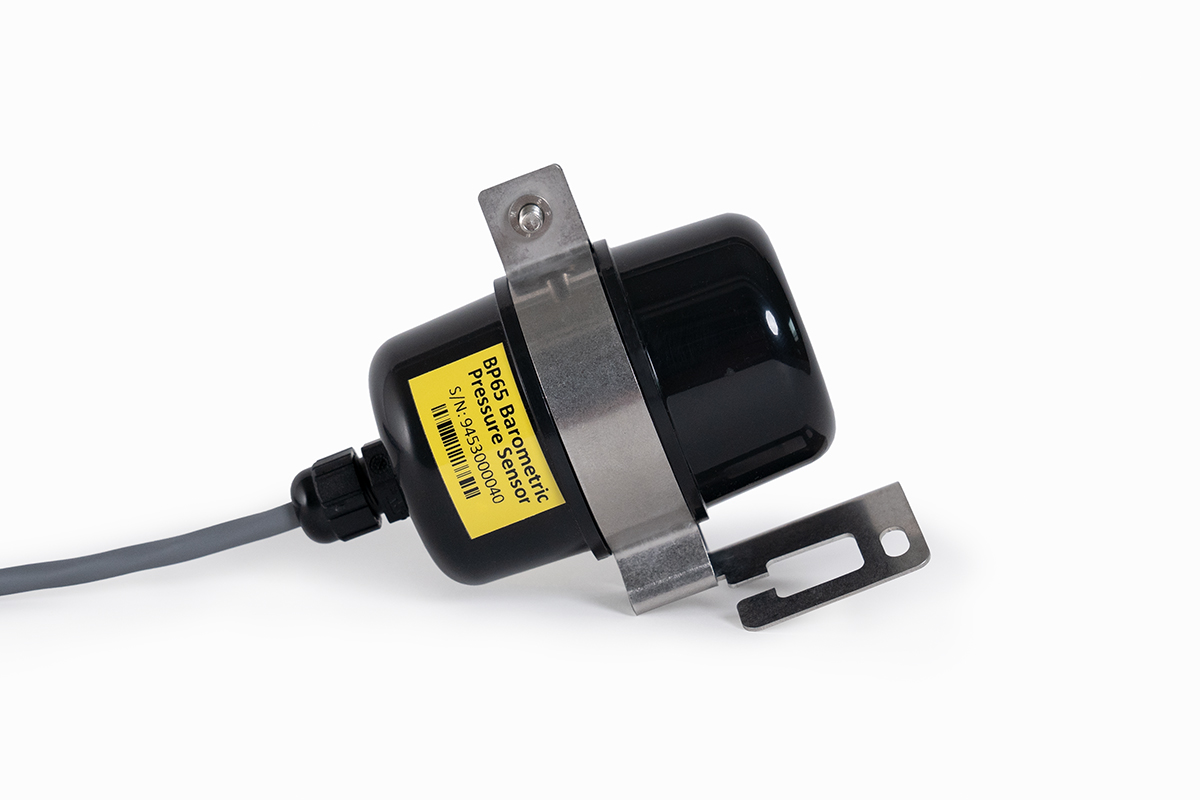
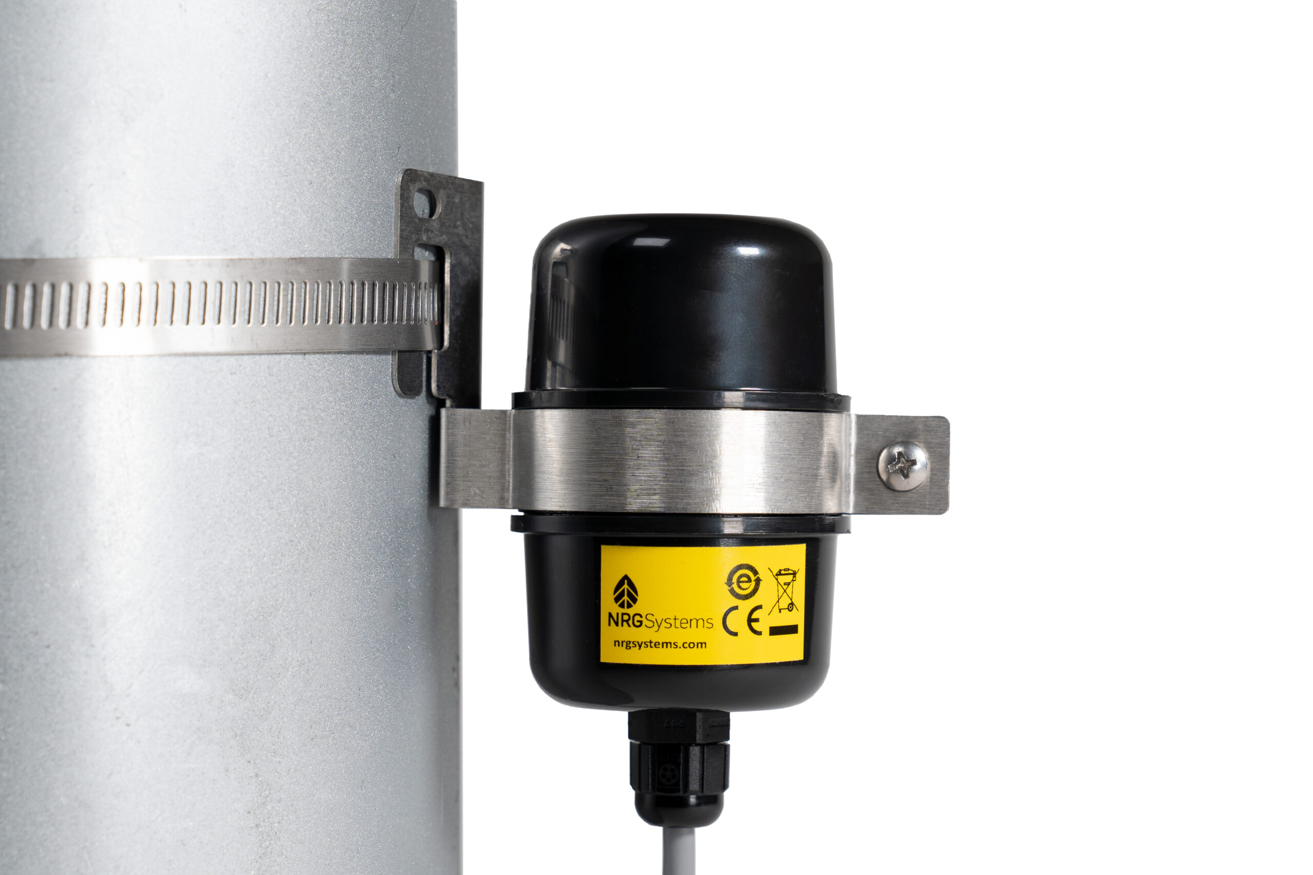
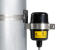
  • A hose clamp is included with each sensor to mount sensor directly to met tower beneath a data logger shelter box.
  • An optional mounting bracket is sold separately for secure mounting up-tower.
  • For maximum protection against ingress, place sensor inside data logger shelter box. Recommended but not required.
  • A hose clamp is included with each sensor to mount sensor directly to met tower beneath a data logger shelter box.
  • An optional mounting bracket is sold separately for secure mounting up-tower.
  • For maximum protection against ingress, place sensor inside data logger shelter box. Recommended but not required.
  • A hose clamp is included with each sensor to mount sensor directly to met tower beneath a data logger shelter box.
  • An optional mounting bracket is sold separately for secure mounting up-tower.
  • For maximum protection against ingress, place sensor inside data logger shelter box. Recommended but not required.
  • A hose clamp is included with each sensor to mount sensor directly to met tower beneath a data logger shelter box.
  • An optional mounting bracket is sold separately for secure mounting up-tower.
  • For maximum protection against ingress, place sensor inside data logger shelter box. Recommended but not required.
  • A hose clamp is included with each sensor to mount sensor directly to met tower beneath a data logger shelter box.
  • An optional mounting bracket is sold separately for secure mounting up-tower.
Tools required
  • 8 mm (5/16 inch) nut driver or flat blade screwdriver
  • 8 mm (5/16 inch) nut driver or flat blade screwdriver
  • 8 mm (5/16 inch) nut driver or flat blade screwdriver
  • 8 mm (5/16 inch) nut driver or flat blade screwdriver
  • 8 mm (5/16 inch) nut driver or flat blade screwdriver
Accessories
  • BP65 Mounting Bracket available for secure up-tower installations.
  • BP65 Mounting Bracket available for secure up-tower installations.
  • BP65 Mounting Bracket available for secure up-tower installations.
  • BP65 Mounting Bracket available for secure up-tower installations.
  • BP65 Mounting Bracket available for secure up-tower installations.
Wiring Wire leads:
  • Signal (clear wire)
  • Ground (black wire)Excitation (red wire)
  • Shield wire for earth ground
Wire leads:
  • Signal (clear wire)
  • Ground (black wire)Excitation (red wire)
  • Shield wire for earth ground
Wire leads:
  • Signal (clear wire)
  • Ground (black wire)Excitation (red wire)
  • Shield wire for earth ground
Wire leads:
  • Signal (clear wire)
  • Ground (black wire)Excitation (red wire)
  • Shield wire for earth ground
Wire leads:
  • Signal (clear wire)
  • Ground (black wire)Excitation (red wire)
  • Shield wire for earth ground
Environmental
Operating temperature range
  • -40 to 70°C (-40 to 158°F)
  • -40 to 70°C (-40 to 158°F)
  • -40 to 70°C (-40 to 158°F)
  • -40 to 70°C (-40 to 158°F)
  • -40 to 70°C (-40 to 158°F)
Operating humidity range
  • 0 to 100% RH
  • 0 to 100% RH
  • 0 to 100% RH
  • 0 to 100% RH
  • 0 to 100% RH
Lifespan
  • 2 years +
  • 2 years +
  • 2 years +
  • 2 years +
  • 2 years +
Other
  • IP55 Rated
  • IP55 Rated
  • IP55 Rated
  • IP55 Rated
  • IP55 Rated
Physical
Cable length
  • 1.5m (5 ft)
  • 1.5m (5 ft)
  • 67m (220 ft)
  • 90m (295 ft)
  • 110m (361 ft)
Weight
  • 0.12 kg (0.27 lbs)
  • 0.12 kg (0.27 lbs)
  • 2.55 kg (5.63 lbs)
  • 3.41 kg (7.51 lbs)
  • 4.15 kg (9.14 lbs)
Dimensions
  • 55 mm (2.15") diameter x 101 mm (4.0") tall including cable gland
  • 55 mm (2.15") diameter x 101 mm (4.0") tall including cable gland
  • 55 mm (2.15") diameter x 101 mm (4.0") tall including cable gland
  • 55 mm (2.15") diameter x 101 mm (4.0") tall including cable gland
  • 55 mm (2.15") diameter x 101 mm (4.0") tall including cable gland
Materials
Cable
  • 3 conductor 22 AWG, with overall foil shield and drain wire, PVC jacket
  • 3 conductor 22 AWG, with overall foil shield and drain wire, PVC jacket
  • 3 conductor 22 AWG, with overall foil shield and drain wire, PVC jacket
  • 3 conductor 22 AWG, with overall foil shield and drain wire, PVC jacket
  • 3 conductor 22 AWG, with overall foil shield and drain wire, PVC jacket
Enclosure
  • Weatherproof black ASA
  • Weatherproof black ASA
n/a
  • Weatherproof black ASA
  • Weatherproof black ASA
Customer care

Hai bisogno di maggiori informazioni su questo prodotto?

Compila il modulo: un nostro addetto prenderà in carico la tua richiesta e ti risponderà nel più breve tempo possibile.